Akira
Just about every good frame (and not so good frame) gets cloned, and boy did Siccario get cloned a lot. At this point I don’t even get upset any more, because A: I can’t stop it, and B: they’re inevitably worse. And in this case that was true again, the Siccario clones were just uglier copies.
Except for one. Mark Weber’s beautiful Tilt Angle frame was handmade with curved tubular arms, which solved Siccario’s main weakness: arms that flex more side to side than up and down. Fortunately for me, it was also heavier and pricier. Still, it bothered me that there was something out there that had some superior features.
I contacted Mark about producing my own version. I’ve always admired the tubes on racing bicycles. They vary in profile and wall thickness depending on the forces exerted on it at specific points. I thought it’d be really cool to make an arm with variable cross sections along its length instead of a simple extruded tube. I drew something up and asked Mark if he could produce it.

Mark thought he could, but he warned me about prossible resonance with a tubed arm. I’ve had lots of issues with resonance with enclosed frames before, but on the other hand, don’t all heavy lift drones have tube arms? Mark thought it was pretty much a crapshoot, and he wasn’t sure there was another way to test a design other than trial and error. The thought of making an expensive molded arm just to end up with a flyaway frame terrified me.
At the same time I was chatting with Oscar Nilsson and Johan Eriksson of Madkwads. David Gu had connected me with them to see what we could do with different grade carbon and layup angles on arms. I mentioned my tubular arm idea and Johan said he thought 2 1/2 d would be a way around this problem. He didn’t need to say another word. I instantly went to the drawing board.
The idea is to mold a curved carbon sheet, then CNC it. That way the arm could vary in both width and thickness along its length so it could resist flex in both directions. And since it’d be flat at each end, it would mount simply with screws with no need for cutouts and clamps. And of course, being solid, there’d be no danger of resonant vibrations. And best of all, continuous fibers would run along the entire length of the arm. It really could be the best of all worlds.

The arm is 10mm at the motor, 16mm at the body. The change in thickness meant Oscar was going to have lots of fun laying up the carbon sheets.
By this time I’d already made Thicc3, so I went with the same arm mounting: first you screw the arm to the bottom plate with 2 M3’s. Wire it all up, and then screw on the top plate with 1 M4. The M4’s add lots more rigidity and clamping strength than the M3’s. While Siccario needed no landing gear, the taller stators of these big motors meant a little more clearance was necessary. I drew up little feet that cover the M3’s and are held on with a second M4 nut, just like Thicc3. Of course, there’s an M4 nut that contacts the bottom plate for maximum rigidity.

Arms stay attached with the top off.

The top plate bypasses the M3 screw heads. A big M4 clamps it all together.

This is how the landing gear works. Bolt it together with 2 M3’s and 1 M4, then slip the gear over the M4 and secure with a second nut.
The motor mount is the same catdog idea used on Thicc motor mounts. After a few refinements Oscar got cracking on the big aluminum molds needed to make a sheet.
With the arm finalized I moved on to the rest of the frame. This was to be a 9” frame for 31xx motors, so the layout was pretty Siccario-like with a little beefing up.
I did, however, run into a bit of a snag. The arm mounting points really conflicted with the layout of my universal cam mount, and there was nothing I could do to resolve it. I really wanted it to be compatible with the Swol or Siccario cam mounts, but I just couldn’t make it happen. Troy and I were chatting one day about James Near’s mount and I realized that it would be so easy to incorporate it into this frame. On top of that, James’ mount is super low profile so that this whole thing would be really easy to put in a case. The three of us got into a chat and I came up with a sliding t-nut for easier fore/aft adjustment and that was the final piece of the puzzle.


In this iteration I had motor mounts above and below. Oscar reassured me that he had no problem milling out the bottoms of the arms, so the final version has Thicc-style motor mounting, where there’s only an extra piece of carbon below.

Sliding nuts make for easy fore/aft adjustments.
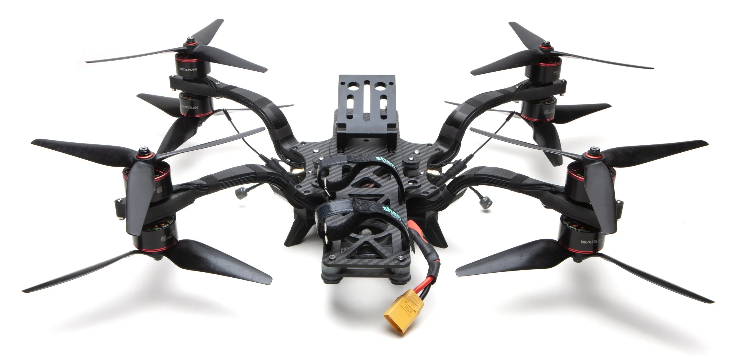
Oscar ordered two huge blocks of aluminum to cnc into the molds of the curved sheet. He also had to get all new bits to cnc the sheets into arms in 3d space. We also ordered some super high modulus carbon. There was lots of trial and error but eventually I got the first set of arms in hand. And…they were ridiculously stiff, coming in at 80g each. Clearly they could go on a diet, but for the time being they were perfect for a first build.


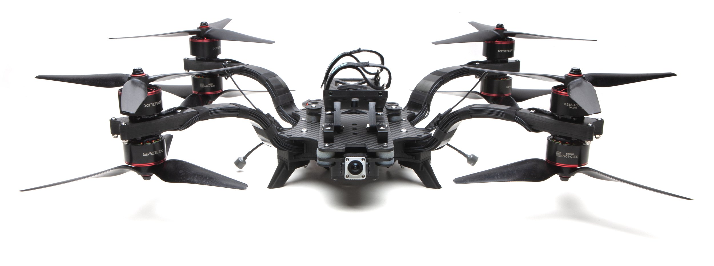
Xnova was kind enough to donate some motors to the cause, and it was super exciting to get some high quality prototypes on the build.

Look at that low serial number. The ends of the arms are a big gnarly, every part of this process is brand new.
Clint got crackin’ on the build, with the usual Matek 722hd and Hobbywing 60a. I drew up a Crossfire mount that put one antenna on each side of the camera so one will always be unobscured by the camera (a Banner Drones idea).

The end result was an absolute beast, coming in at 2259g. Test flights went well, and the spectral analyser was super clean. The frame’s as stiff as it feels.

That’s a distinctive shadow.

So, the next step was to put those arms on a diet. Since they’re already absurdly stiff, my first thought was to make it 10mm thick all the way down. That would simplify the layup process for Oscar.

I’m quite sure that this arm would be stiff enough, but I hated losing the aesthetics and strength of a tapering arm. Then it occurred to me that I could split the arm into two 5mm halves. The layup would still consist of complete sheets, Oscar would just have to machine a metal plug for the gap.

The green part would be a 10mm carbon spacer, the yellow part would either be empty space or a vibration damping insert.
I talked to Oscar and he said that instead of a metal plug, silicone could be used in the gap. Silicone would expand while the carbon is heated and compressed, so it would actually provide more compression than a metal plug. It would also be easier to use and remove. I mentioned that the triangulated arm reminded me of Oscar’s frame, only on a different axis. And that got me to wishing the triangulation extended farther down my arm, so that it could have the rigidity of a much thicker arm. So I came up with this crazy idea.

And then I thought I could 3d print a super lightweight damping insert using foaming TPU. And now that the flat final run of the arm had gotten so short, I wondered if it could be thinned down to 8mm, with 4mm halves.

The thought of slimming it down so much scared me, so Oscar suggested I print one out so I could get a feel of what it might be like IRL.

PLA with a TPU insert.
The part felt pretty good, but it was hard to predict how it would really feel with that super high modulus carbon. So I did a Solidworks simulation on it and it actually outperformed the original by a little bit, with a weight savings of 23g per arm!


A 10/5mm version of the same design would be almost 80% stiffer than the original, and it was really tempting to take the conservative route. But then I realized that I have so many options with the insert. It could be a thin cnc’d carbon piece, or it could be printed in PLA instead of TPU. So I decided to trust the Solidworks results and move forward with the 8/4mm version. It was a super risky and expensive move, but I knew I couldn’t live with myself if I didn’t try it.
Unfortunately the simulation didn’t hold in real life (damn you Solidworks). The split version proved to be too flexy, so we proceeded with the 10mm version. Time for yet another mold…
The 10mm arms finally arrived and they felt every bit as stiff as the 16/10mm original version, while losing 13g each. Hallelujah! It’s been nine months since I started this thing and it finally feels like I can see the finish line. I sent one frame each to Troy of Quad Standard Labs and Sergi of RRFPV.

Thanks to the way the frame comes together I could swap one arm at a time without opening the whole thing up. The whole process should’ve been quick and painless but one motor had a stripped screw and one of the M4’s had damaged threads. After some light hammering and dremeling I was finally done.

Trying to avoid metal dust while dremeling.

Getting closer to production level finish. Oscar’s still experimenting with materials and tooling.
I put it through a Brian White tuning and got it flying absolutely perfectly. Good to get the PID Toolbox Guy seal of approval. One interesting thing Brian found, latency was almost equal on pitch and roll, which is unusual for this layout, since there’s way more mass spread out on the pitch axis compared to roll. We figured it must be the greater authority with the bigger motors. Here’s that tune for you to use as a starting point. Keep in mind that the tune will vary with the motors, props and payload you use. My best advice is to get in touch with Brian for best results.
Meanwhile feedback from Troy and Sergi started coming in. Troy noted that the middle damper interfered with access to the DAC mount’s adjustment screw. He also asked for more forward movement for the mount. Sergi built his for 12S with APD’s. He asked for nose and side protection a la Siccario, and a sturdier FPV cam mount.

That middle damper blocks the adjustment screw of the cam mount. Damn.
I’d been toying with the idea of a full sized clean plate, and I figured this was as good a time to go for it as ever. I redrew all the plates, changing some spacing so that the clean plate can be reversible (yes I stole that from the QAV). Dampers take up a lot of space at the ends, so I came up with the idea of inverting those dampers so the carbon caps won’t interfere with the cam mount and the battery.

Tilta mounting holes added for good measure. The second set of middle damper mounting holes are for when the plate is reversed.

Inverted dampers save space on top. Pressed nuts in the clean plate mean you won’t need a nut driver to adjust the dampers.
I’d made some aluminum FPV cam mounts for Thicc and those turned out real nice. My first impulse was to use those here, but I decided to make new ones that would integrate seamlessly with a nose guard. I drew up a TPU guard that would mesh with the aluminum bits, and added a seal for the air unit, so that it would be ventilated on both sides but sealed as well.


The air unit is sealed against the top plate. Other holes can be taped over depending on how much sealing or cooling you want.

The bottom of the air unit is also open for ventilation. The cam mount is provisionally printed with PLA while waiting for the aluminum parts to arrive.
As for the sides, I drew up a guard that doubled as Immortal T and SMA mounts. Both sets of antennas will be well placed, and one set will always be unobstructed by the camera.

The guard is slightly thicker and stronger by the SMA mount. Those two little nubs add a little compression to keep it snug.

I love how clean the front and sides are. The rear is still open for cooling.
And then the anodized aluminum fpv cam mounts came in, and they were really nice.

And with the arrival of those last bits it was finally time for full beauty shots.

2182g as pictured.


There’s the reversible clean plate in action.
It’s hard to believe but it’s been over a year since I started designing this baby. Molded arms take a lot of time! I’m incredibly proud of this one, I think it’s my finest work yet. The arms are the main feature, of course. They’re incredibly stiff in every direction, they have continuous carbon fibers running through them, and they’re as simple to mount as can be. The frame is both functional and (IMO) really beautiful. It’s also really uncomplicated, just 21 pieces of carbon (and that’s including the 6 damper washers) and not much hardware. It’s nice and light, about 700g for the frame and 154g for the DAC cam mount. It’s Ronin ready, with Tilta mounting holes on the clean plate. Unlike Swol and Siccario, you can pop the top off and the arms stay attached for quick and painless maintenance. It’s only 14 cm tall so it transports well. And most importantly, it shares Siccario’s original concept, aligning the center of mass and drag with the center of thrust for optimal flight characteristics. I can’t wait to see these babies go out in the world and do work.