Tweaker Beginner Build Guide
How to build a Tweaker or similar mini racing quadcopter.
I get Shopify alerts for every sale, and I was quite surprised to see that my college roommate Martin had bought a Tweaker. I got in touch and found out that he's never built or flown anything, and I realized that I would be walking him through the whole process. I had a 1306 Tweaker build pending, so I thought I might as well make a beginner's guide for Martin and whoever else might be interested. So here we go.
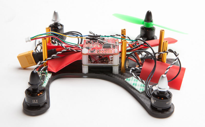
Start by screwing in the standoffs to the base. On the FPVA edition you’ll use the 8mm screws for the bottom. Use blue threadlock here and on the motors. Get the plastic standoffs for the FC on now too. I’ll be putting my D4r-ii receiver under the pdb so I’m making sure that those standoffs are tall enough for it.

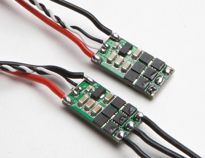
I’m using SN20’s for this build. Remove the heatshrink and desolder the 3 motor leads. If you’re using Kisses you’ll be soldering on leads for power and signal, as well as bridging the Oneshot jumpers.
Prep the pdb by tinning the pads. They should be nice and shiny. I’m using the 4power pdb from getfpv here. I like it ‘cause you can solder a Pololu 5v stepdown right to it to supply power to the Naze. Solder the header to the Pololu.
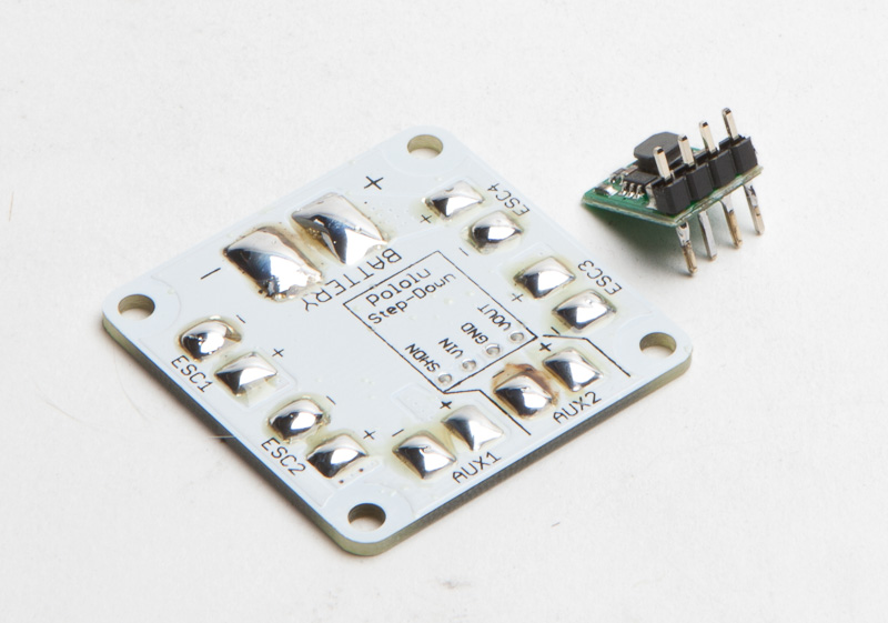
Bridge the SHDN pin on the Pololu to the VIN pin next to it. This is absolutely essential. Trim off the excess on the pins when done.

Drop the pdb onto the frame and measure where to cut the power leads. Note that on the rear esc’s the leads straddle the rear standoff.

Cut the leads, tin them, and solder them to the pdb. Repeat for the other esc’s.

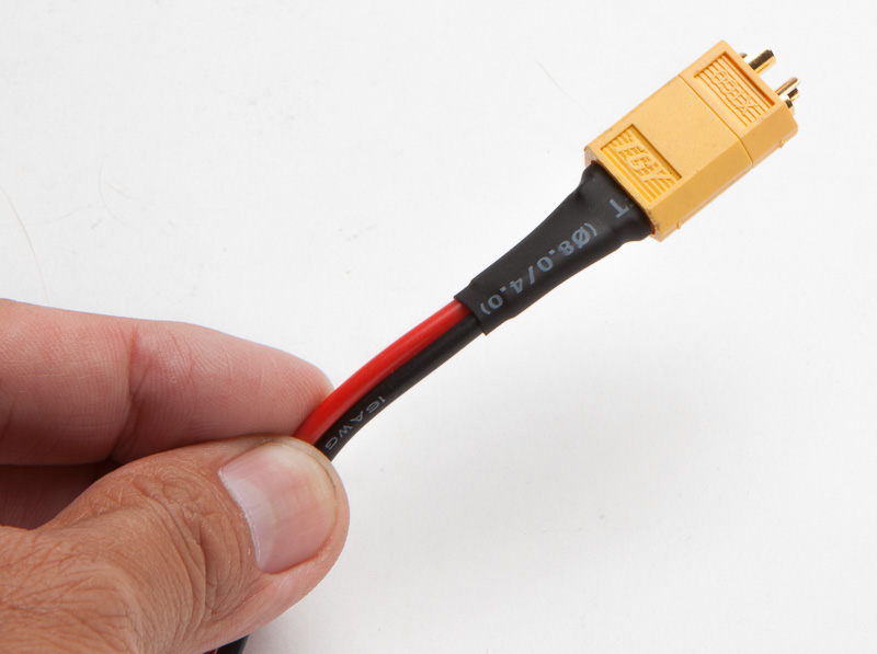
Make an XT60 pigtail. 16g wire is plenty for this power train. I plug the XT60 into a male plug and clamp the male plug so the female plug isn’t deformed by the heat of soldering.

I add an extra layer of heatshrink over both wires because this pigtail will go through a hole in the frame. There’s just the slightest chance the frame will cut both wires in a hard crash, and the carbon would then short the battery. A little extra protection here can’t hurt.
Solder the pigtail to the pdb. Leave plenty of clearance around the plastic screws, there’ll be standoffs screwed into them.

Lay down double stick foam on the arms for the esc’s. Screw on your motors. These DYS motors have CW and CCW nuts, make sure motor rotation tightens the nuts.

Slip heatshrink over the esc’s. The back right motor is motor #1. Solder the three motor leads to the esc. Hold off on the other 3 motors until we check the rotation direction on this one. If you're using Kiss or are able to reverse motor direction in BLHeli suite then solder them all up now.

Solder leads to the AUX2 pads. These will supply 5v to the FC. I’m using 2 wires off a servo lead, any light gauge wire will do.

Solder that lead to the + and - pads for motor #1 on the Naze.

Tin the ground, power, and signal #1 pads on the Naze and attach a servo lead to them. We’ll be using ppm on the D4r-ii so we’ll only need one signal wire. Make sure you're mounting the Naze with the USB plug pointing to the side.

Bridge 3 and 4 on the receiver with the supplied jumper. This switches the D4R-ii from pwm to ppm, which means it transmits up to 8 channels on one signal wire.
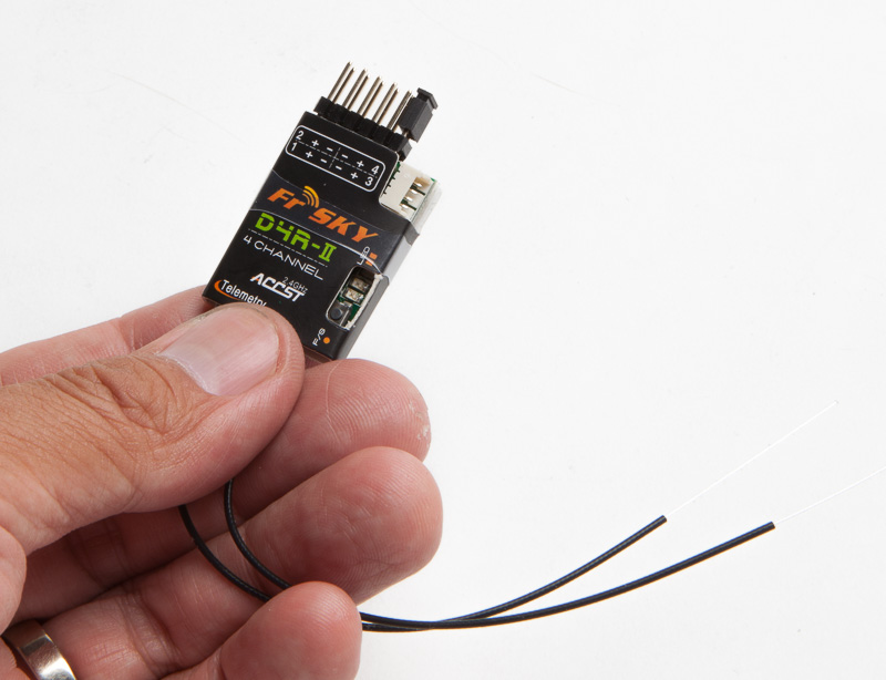
Line up the receiver to the hole in the bottom plate so that the bind button is accessible, and attach it to the pdb with some double sided tape.

Solder on your VTX wiring harness. Every VTX is going to be slightly different. I’m using a TS5823, so power and ground go to the AUX 1 pads. In addition the audio lead is grounded as well. 5V out and video signal goes to the camera, while the camera’s ground is grounded to AUX 1.

I’m direct soldering the signal and ground wires from the esc to the fc. This is nice on this build since there’s less room on a 180, but if you’re not experienced with soldering it’s best to use headers and plugs. You have to solder the grounds with the SN20’s, no need with Kiss. Feel free to judge the soldering here.

Now with one motor and esc wired up we can test motor rotation. First we need to flash the Naze with the latest firmware. Download Cleanflight from the Chrome store, plug in your Naze. Go to Firmware Flasher and choose the latest stable build for Naze.

Click on Load Firmware (Online), then Flash Firmware. Then connect.

You're in! Lay the copter flat and Calibrate Accelerometer. Keep still you dirty Tweaker.

Next go to the Configuration tab. Yaw adjustment will be 90 or -90 depending on which way you mounted your board. Choose one, go back to the setup tab and move the copter around to see if it's aligned with the 3d model.

Now head to the Motors tab and click on the 'I understand the risks' box. Your props are off, right? Plug in a battery and spool up motor #1 and check its rotation direction. If it’s correct then move on to the rest. If not, switch two of the leads (if you're using Kiss then solder jumper 2). In this case motor 1 was spinning the right way, so I did motor 3 the same way (no crosses), and crossed one for 2 and 4 as seen below.

All motors wired up. Note that I’ll have to remove the rear standoffs to slide the heatshrink over the rear esc’s. This is pretty much the worst part of building something this small.

The rest of the esc signal and ground leads soldered up. Leave some slack in these wires so you’ll be able to lift the Naze up for repairs. It’s cleaner with shorter wires but repairs will be a major pain.
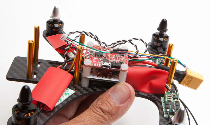
Heat shrink heat shrunk, esc’s taped down and zip tied. Do not skip this step. Even though these components are very light you’re pulling massive G’s going from 30-40mph to 0 in a hard crash, and every time the esc’s shift your solder joints will be yanked until they finally fail, inevitably in midair.

Ryan Gury uses 4:1 or even 6:1 heatshrink that’ll slide over the motors and wrap around the entire arm and esc.

None more black.
Go back to Cleanflight and calibrate your esc's. Go to the Motors tab, raise the Master slider to the top, plug in your battery. Wait for the esc tones and slide the Master switch down. For BLHeli esc's raise and lower the slider again. Unplug and plug the battery, and test that all motors spin up at the same minimum throttle.

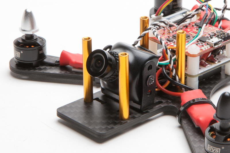
The Tweaker comes with a 20 degree cam mount, but there’s also a 3mm hole in the middle if you have one of these cam brackets. This is great for quick tilt angle changes.
Slap the top plate on, use a couple zip ties for the antennas, and you are done!


Here's some starter pid's to get you in the vicinity. If you think I'm writing a beginner's guide to pid tuning you're nuts.

This is by no means definitive, it's a bare bones guide that'll get you in the air. It's literally the least you can do to get flying.
Don't direct solder to the FC unless you're confident with your soldering skills. If I was to build another Tweaker with these same exact parts (knowing the motor rotation direction) I'd solder the motors to the esc's first, heatshrink the esc's, then mount the motors to the frame, and then solder the esc power and signal leads. This would also be the way to go if you use BLHeli suite to reverse motor direction.
Finally I want to acknowledge my club FPV Addiction, a great bunch of guys with a diverse collection of skills that I learn from every day. I am by no means an expert in this, but with their help I get by. Give them a follow on Instagram.
https://instagram.com/dronekraft/
https://instagram.com/jns_steve/
https://instagram.com/luckylegacy13/
https://instagram.com/mach_one_fpv/
https://instagram.com/onfourblades/
https://instagram.com/shane_fpv/
And check out Alex Walsh's page for builds that are true works of art.
Here's a build log by Peter Brown that includes some cool 3d printed parts.