Siccario
You know how car companies roll out a new model annually, so they give it a chance to sell for a year before rolling out something better? Yeah, we don’t do that. Five minutes after Gab perfected his Thicc he asked for something new.
Gab wanted something that could take advantage of the Z Cam’s slim form factor, by nestling the cam between the props for prop free video at 0 or even negative tilt, Gab’s preferred way to shoot downhill sports. This would also tighten up rotational mass for better handling.
The center of thrust on an X8, unlike a quad, goes right through the middle of the arms. So if you want to put the camera right in line of the center of thrust, well, you got a problem. So I thought of this:

Now the tough part is, how do you make that arm? The easiest way would be to cut it out of 10mm carbon, then drill mounting holes along the carbon layup.

Unfortunately, that would cause the carbon to delaminate, so we’re going to have to do this the hard way, with interlocking pieces a la box frames. I originally conceived of arms made of two vertical 4mm pieces with cross braces, but fortunately Gab asked ‘why not just make it a single 10mm piece?’ Duh.
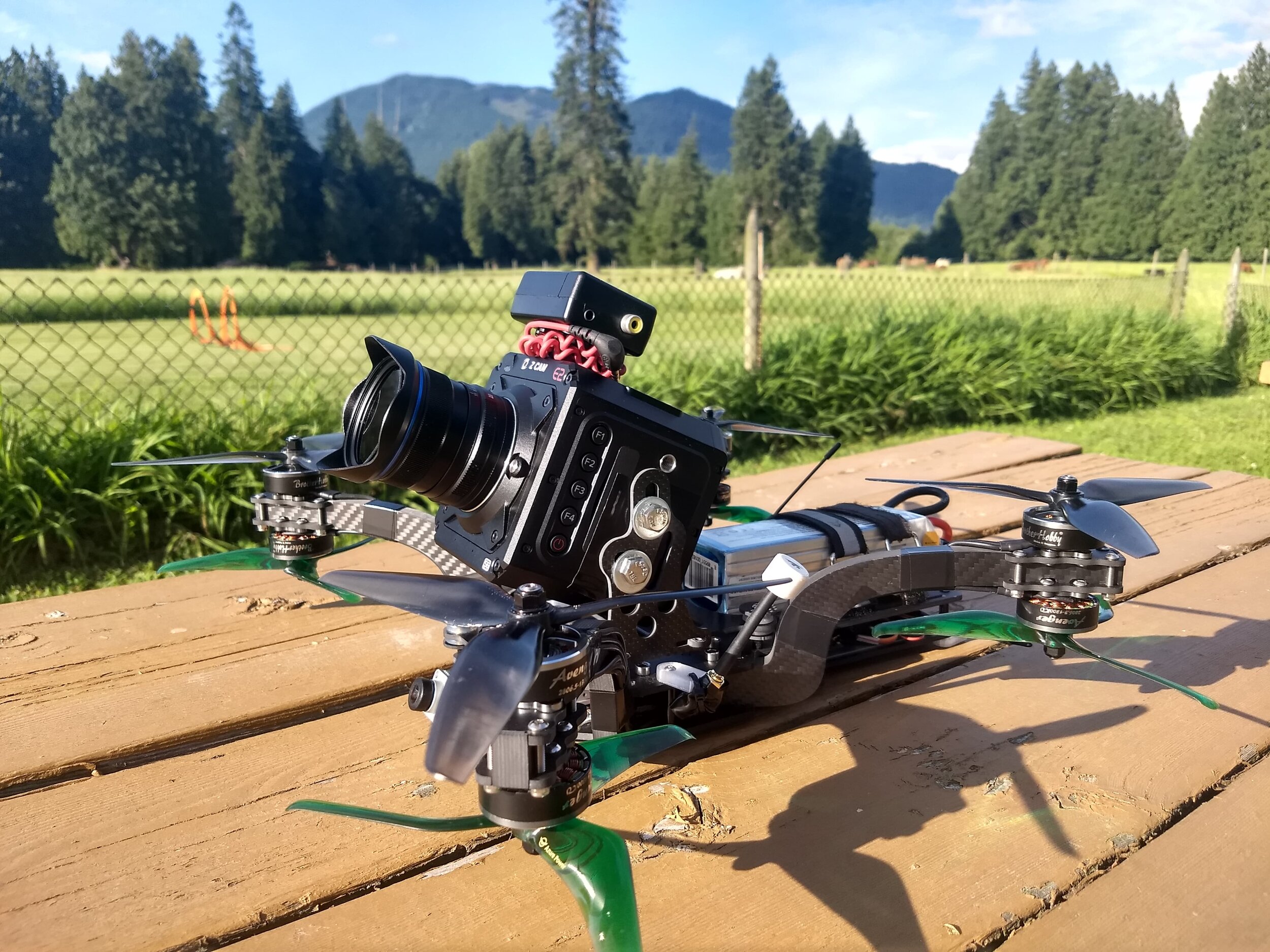
The Thicc motor layout flies great so we’re starting with that. We know the front of the lens has to be approximately in line with the front motors for unobstructed video. With the battery behind the cam, this works out almost perfectly for CG. The Z Cam has side mounting holes, which are great for changing cam tilt. This also means the cam plate can be parallel with the top plate, which will make experimenting with dampers much easier. This also gives us a simple blank canvas for the cam plate so we can accommodate different cameras. With those parameters established it was time to get crackin’.
A 20mm stack was enough for the components in Thicc, so I made the arms 20mm tall. The sandwich plates will be 3mm – I couldn’t imagine anything thinner being strong enough.

I wanted the ends of the arms to be a thin as possible, but cutouts for motor screw heads shave off some material, so I could go only so thin.

Four M3’s hold the motor mounts in place. The screws are tangent to the sides of the arms so they lock the plates in laterally as well.
With the arms done it was time to move to the sandwich plates. I prefer flowing lines but I couldn’t get it to look right.

So I went for a more geometric look, and it made much more sense here.

I added the overcuts (round bits can’t cut square inside corners) and this thing’s starting to take shape.

Gab likes how Hydrophobe’s waterproofing makes it a real workhorse, so he asked for the same feature here. Oh boy. I proposed putting a heatsink in back, away from the high stress area around the arms. It would nestle in a relief cut in the carbon, and protrude a half mm above the surface to mesh with a tpu skirt. Two esc’s mount to the heatsink with thermal paste in between, while the fc mounts to the carbon, right in the center of the frame.


Bottom view, the aluminum is exposed to the air for cooling.
Then I added mounting points to screw the heat sink on.

So that’s the main frame sorted. I went ahead and ordered the carbon to make sure the frame is airworthy first, while continuing to brainstorm the cam mount/damping solution. Gab ordered a Z Cam and had it sent to me so I could take measurements.
I did a rough mockup to see how much clearance we’d need for 40 degrees uptilt and 20 down.


Since this frame’s all about tightness and perfect CG, it really bothered me that we’d have to raise the camera 20mm to accommodate the tilt, so I started thinking about a sliding slot system that will keep the camera as low as possible at all angles, and this is what I came up with, using the top and bottom holes.
Then I changed it to using the middle hole and bottom hole instead, which makes the part smaller, locks the camera on a vertical track, and, bonus, it looks like it’s giving you the finger.

We want some fore/aft adjustment to accommodate different lens barrel lengths and fields of view, so I’m hoping the tension from screwing in the camera will be enough to clamp the cam plate and lock the vertical stanchions in place. We’re always concerned with quick adjustments on shoots – you don’t want the crew waiting on you while change cam tilt. This system, if it works, would be really simple. Loosen the camera, set your angle and fore/aft, and re-tighten four screws to lock it all down.

A couple M3’s on the tabs keep the stanchions from falling off but don’t keep them from sliding.
I’m holding off on the cam plate ‘til we figure out the dampers. We might need m3 screw holes, we might need great big grommet holes. Meanwhile, the carbon came in. It’s a bit nerve wracking to cut interlocking parts since tolerances are so critical. Too tight and you’ll be filing, too loose and things are floppy. Luckily I guessed well and everything fit together nicely.


Coupla M4’s clamp down the arms. I didn’t want to take any chances with M3’s. Like the motor mounts, the bolts are tangent to the arms so they brace them laterally as well. It’s rock solid once tightened down.
The frame turned out to be a bit heavy, about 500g, or about 80g more than Thicc. There’s lots of spots for weight savings, so round two could be much lighter.

I keep forgetting about the motor wires. It’s super snug and unbelievably annoying to get those two nuts on, but thankfully it all fits.

I thought I was super slick with those zipties, but it turns out the lower prop hits the wire and ziptie under the arm. Half the motor wires need extending. We’re going to have to ask Brother Hobby for longer wires.

This thing’s a bit of a nightmare to build since you can’t assemble it until you have it all wired up. Zipties hold the arms in place while you build. I opted to forego waterproofing for now so I stacked the esc’s. If I’d mounted the second esc behind the first one I’d have to extend the signal wires to the fc, and that’s just too much splicing for one build.

So. Much. Soldering. I left all the wires super long ‘cause it’s a proto and you never know what’s going to change. I went with my trusty double xt60 parallel battery setup so I don’t have to buy big batteries.
I got MMCX to SMA extensions to get the antennas out as wide as possible. I drew up SMA mounts which lean up against the arm so the antenna can’t rotate into the props.

Good thing I left the wires long. If I build it again I’d have cable routing sorted much better. With the antenna mounts on there’s no access to the fc’s usb (foreshadowing).
I had initially dropped a CLI dump from my Thicc on to this fc, but I wasn’t able to get an rx connection. I thought it might be a Betaflight 4.2 vs 4.1 issue, so reset all the settings and started fresh. It didn’t work. Luckily Troy Naquin saved the day – I had the wrong baud rate set for the Air Unit. Finally it was all set up and ready to be assembled.
Closing it up was an adventure, as you can imagine. You have four floppy arms you have to simultaneously drop into their slots while making sure no wires get pinched in the process. I got it done with a couple helping hands from my daughter.
I took it out for a quick maiden, and immediately realized that it had stock pids – I neglected to change the pids when I reset the fc. It still flew pretty well but a little slop was definitely evident. I brought it home and went through the arduous process of opening and closing it (I managed it solo this time) to get the Thicc pids on there.

This thing’s so bizarre looking in the air.
Here it is the next day. The fields were all locked up so I had to fly it easy in this open spot. That’s Justin telling me to get it in the sun and kick up some dust.
And here’s some more aggressive flying the next day, good to see the frame hold together just fine.
Gab got his and confirmed that he likes the way it flies, time to move to the cam mount situation. He’s been working insanely hard at finding a perfect damping solution on Thicc, and we’ll be taking advantage of all the knowledge he gained in the process here.
He roughed in the camera and battery to test for unobstructed video and balance, and we found that my initial guess was a bit off. The camera will sit a bit more forward, so for round 2 I’ll have to extend the nose a little bit. We also figured that the front damper mount points could be a bit more spread out, so the nose will be a bit wider as well.
We decided the damper design would basically be a big grommet, just like fc grommets. The pass through hole will be 9mm, and the outer diameter about 18mm. With those dimensions I drew this up.

I also started to put it on a diet. The main frame will go through extensive changes once we learn everything we can from this iteration, so only the arm gets work for now. I like this geometric progression. The holes will be handy for cable routing as well, a good way to keep them away from props.

I’ve never had a frame so fundamentally tied to a camera before, so that it only looks right with the camera mounted. I dropped in a rough render of the zcam just to see it all together.


Gab got his cam mount cut locally by CNC Madness and finally we got to see this baby in its full glory.
I mocked up a cross section of the Zcam to confirm that my clamping system would work.

Gab confirmed that it flew well, but a bit heavy. We put our heads together and listed all the changes for V2:
Extend and widen the front damper mounting points. Allow more forward travel for the camera to allow for unobstructed video at negative tilt.
Lose weight: add holes to arms, narrow the tail, mill out the 3mm plates where strength isn’t needed.
Heat management: Gab found a filament (TCPoly Ice9 Flex) that can work as a heat sink, so we’re losing the aluminum plate. We might even switch to Kotking instead of a TPU skirt for waterproofing, in which case we won’t be enclosing the electronics and won’t need heatsinks.
V2
With those changes in mind I got back to work. I originally thought the second esc would be mounted to the aluminum in the tail, which meant the tail had to be pretty wide. Now we’ve moved both esc’s up a slot so the tail isn’t housing anything any more, so I narrowed it way down to the width of a 3300mAh battery. The bottom plate only needs to extend halfway down the battery, more weight dropped.
I extended the top plate for the front dampers, and gave them a full 16mm circle for the grommets to rest upon.

Narrowing it down.


If you look carefully you can see the milled out parts in the two big plates.

If we go with the 3d printed heatsinks they’ll be here.

First test print. This stuff conducts along the layer lines so you have to print this piece vertically so the filament will bring the heat from the inside to the outside.
I had six frames cut. The carbon bits came in and I hurriedly swapped my parts over. But when I tried to screw down the motor mounts I couldn’t get the locknut threads to engage, and that’s when I noticed that my arm drawings were messed up! The little recesses for the screw heads were missing, which means the motor mounts were floating a mm or two above the arms. What a stupid and costly mistake.

No grooves, just sadness.

She pretty tho.
Now, I could re-cut the arms, but they’re 10mm and super expensive. Then I realized I could countersink the motor mounts, which, if you think about it, IS WHAT I SHOULD’VE DONE IN THE FIRST PLACE.
I told my tale of woe to Gab and the testers, and Gab’s response was ‘Why don’t we make the arms fit 8” props if you’re going to recut them’. And I thought, ‘why didn’t you tell me this before I had six frames cut?’ As annoyed as I was I knew well enough that you never go against the siren song of MOAR POWER, so I got to work.
Without the screw head recesses I could narrow the arm vertically while retaining the same strength. And with that thinned down I could also reduce the profile of the arm, so that I could make an 8” arm that was only 8mm longer than the 7” arm. Now you can run all 8’s, all 7’s, or a combination of 8’s and 7’s to maximize power or efficiency.
There was one bit of good news, though. The weight came down to 420g including the damping assembly (V1 was 500 without the damping assembly), just 8g more than Thicc.
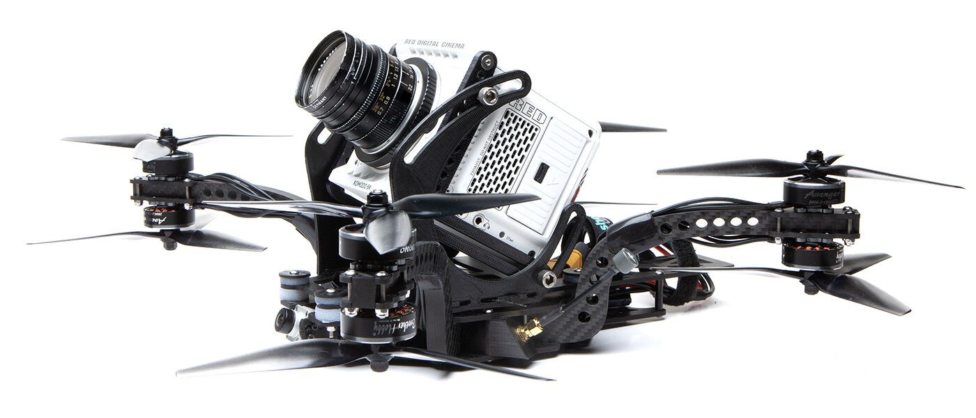
Komodo
So, we started this as a Z Cam drone, but we always had the Komodo in the back of our minds. My buddy Justin had one on preorder (thank heaven for Justin), and he brought it over when he got it. Now, even though I was a pro still photographer for years, video cameras confuse the hell out of me. But even stupid me could see that the Komodo is a game changer. I won’t go on about why since I’m a camera idiot and you have Google, but suffice it to say we’ll have to dedicate our efforts to making this a Komodo carrier now. Good thing it’s a very similar form factor.
The Komodo has two M4 mounting holes on each side at the front of the body. I think those mounting points are so far forward because most users will use big ass lenses and the CG works out better up there, but for our purposes it’s far from optimal. The Z Cam has its mounting points mid-body, and it lines up perfectly for us there.

There are aftermarket ribs for the Komodo that mount to those M4 holes which add 1/4” and 3/8’ mounting points, but they’re super thick. They increase the width of the cam to a whopping 114mm, which makes it too wide to fit between the front arms. I proposed using the Komodo’s M4 holes directly but Justin thought that might wear them out, and camera departments like 1/4” and 3/8” mounts. I was thoroughly flummoxed and then Justin said ‘just make your own adapter’. DUH.
I drew up a 6mm thick aluminum rib that added two 1/4” holes between the M4’s. All looked well until I realized that the 1/4” screws would be blocked by the arms, so you’d have to use a hex head screw and a spanner. Awkward.

So I extended the bracket back for the lower hole. The Komodo has a protrusion on its sides with cooling vents, so the bracket has to be an unsupported L shape.

With the lower hole repositioned everything lined up much better. I didn’t like that unbraced L on the aluminum bracket so I added a thin carbon crossbar that’ll double as a washer for the 1/4” bolts.

Finally! Though the changes were all functional it turned out prettier too.
Dampers
Gab found that Alpha Gel bushings were the best cam damping solution. They are, however, extremely expensive. It might be the height of hubris to think that I can make something as good on my own, but I’m nothing if not stupid and overly optimistic. I found a two part silicone with a shore hardness of A10 (for comparison TPU is around A95) and drew up some grommet molds. They’re essentially identical to the grommets you get on fc’s, but in two pieces.

Molding was surprisingly painless, and no mold release needed.

Way more professional looking than a DIY grommet has a right to be.
One key characteristic of the Alpha Gel bushings is their consistent performance through a range of temperatures. This is a big deal for Gab, who shoots a lot of winter sports. He asked me to stick one of my grommets in the freezer for an hour, and, this is super scientific, it was still pretty soft. So…not b-b-b-bad?
Gab was traveling on a shoot so I couldn’t get these to him right away. In the meantime Stephen Loewinsohn put them on his Thicc and got good results, despite the fact that his mounting method allowed for direct contact between the two halves through the bolt. So, that’s promising.

A New Approach
Thicc came along at the dawn of this ‘Cinelifter’ era, so there’s a bit of a DIY vibe to it. With this new baby we wanted something that’s perfected in all aspects so you can go right out and start working with it, no need to tinker. So Gab, Troy Naquin and I decided to partner up and offer this as a full build only solution instead of a frame kit. This way you’ll get Gab’s expertise with camera damping and SteadXP, and Troy and Quad Standard Labs will manage production, sourcing the best components. We’ll also enlist UAV Tech to create custom tuning packages.
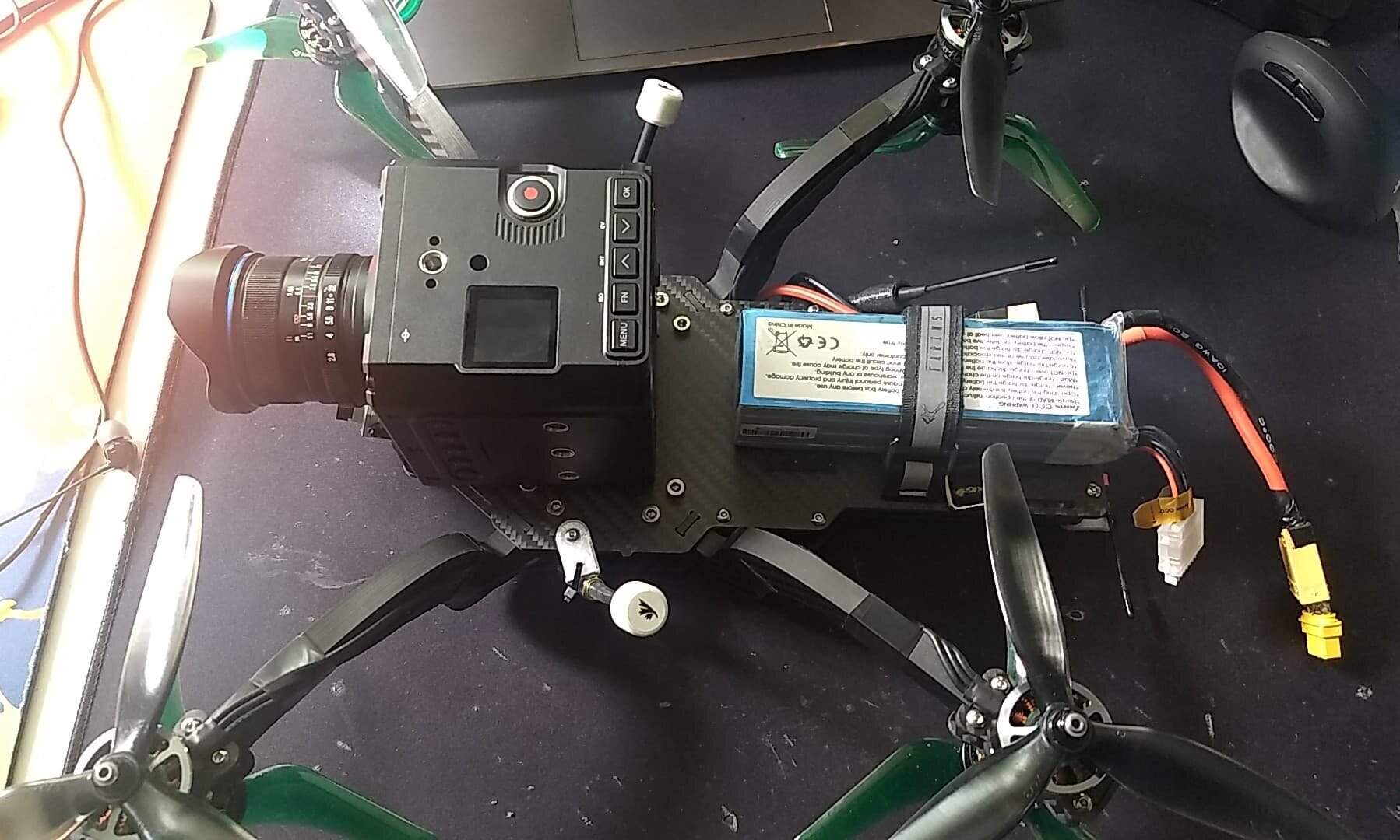
Quick Komodo Test
I convinced Justin to let me do some quick LOS hovering with his Komodo. The Komodo mount’s not in yet but I can strap it to the clean plate to get a quick sense of how well the dampers might work. This thing looks so cool with the Komodo nestled right in the center, so low profile.

Justin set the shutter speed to 1/48, the worst case 180 shutter scenario. The footage looks promising so far. Of course I would’ve loved to fpv it, but that’s one hella expensive and unavailable camera.
Next Iteration
The next batch of carbon came in, and the motor mount is looking better. Countersinking the bolts makes for a much cleaner setup.

The Komodo mounts look nice too, though the 1/4-20 threads turned out to be 1/4-28 threads. I stopped by my hardware store and found that M6 screws work well enough, so that’ll do for now.

Justin brought his Komodo and I bolted it together. The left side went on perfectly, and then this…

I’ve been designing off drawings of the Komodo, and I failed to account for that damn antenna.

That protrusion runs into the stanchion and prevents the camera from tilting up. Ugh. The damn thing was perfect in every other way, too, super snug once the four bolts are tightened. Back to the drawing board. Much sadness.
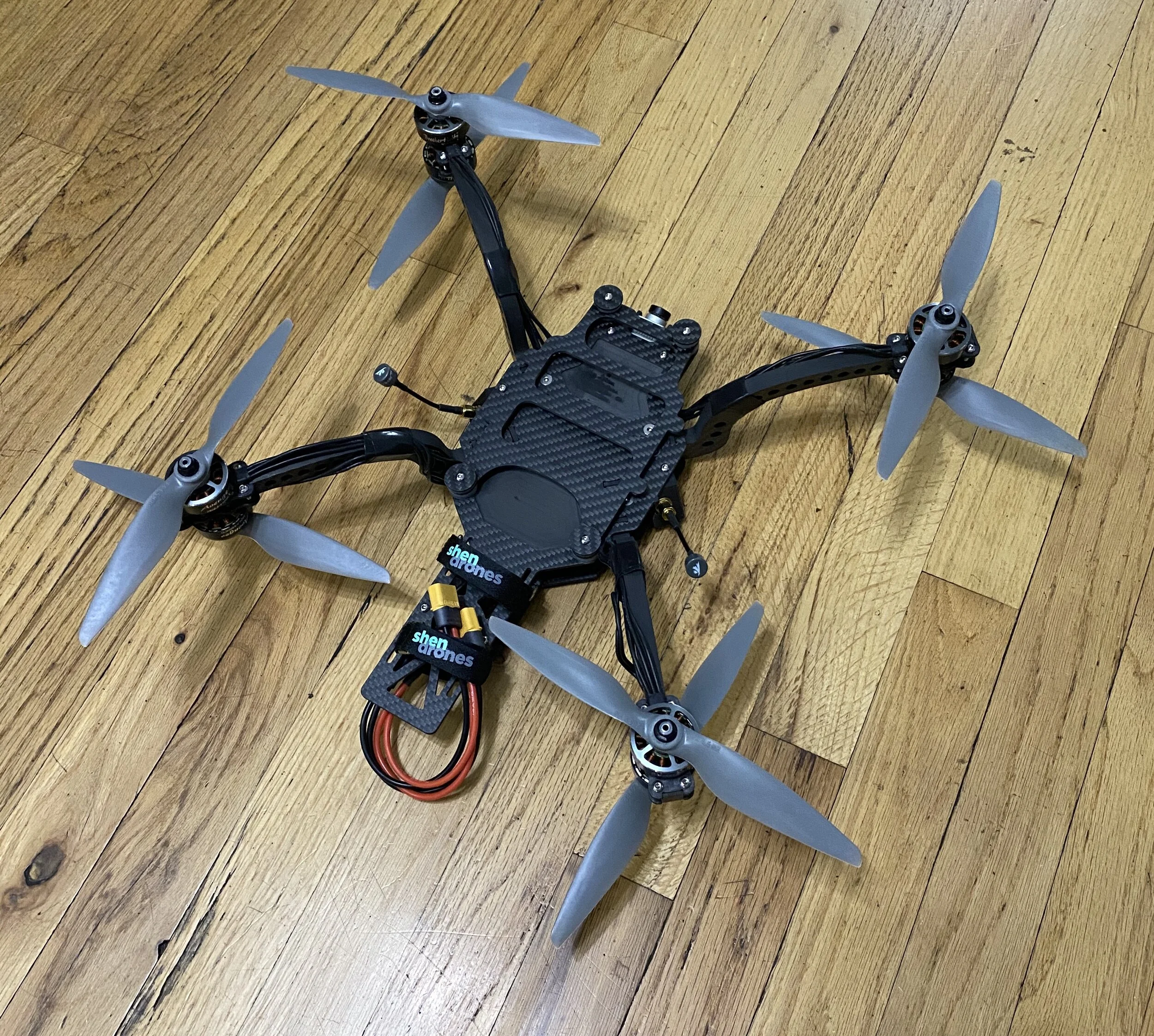
I put the new arms and motor mounts on my build and they’re looking good, so there’s that. I dug up some old APC MR845’s and gave it a quick hover inside. That distinctive sound really takes me back to the bad ol’ days.
Komodo Take 2
After much brainstorming I realized that the only way this can work is with a pair of pivots instead of tracks. A pivot at the rear bottom corner will handle uptilt and a pivot up front will handle downtilt. After that it was just a matter of trying pivot locations for the front to clear the antenna.

40 degrees up, 18 down. That crazy Komodo mount has a Julie Taymor vibe.
And then I realized that we need clearance for the audio jack to use SteadXP. So my pretty previous iteration, which blocked the audio jack, wouldn’t have worked anyway. Christ this thing is complicated.
I printed up the parts and we mocked it up for some beauty shots.


The preorder listing is up at QSL, go reserve yours! We’ll be test flying the Komodo in a week or so.
2/14/21 Update
We started Siccario as a full build only partnership with Gab and QSL, then by popular demand we opened up frame sales, here.
Gab had been talking about a live broadcast drone for ages, our conversations always seemed to end on us trying to figure out how to make it happen. He told me he had a client that wanted live stabilized HD footage, so fixing the footage in post wasn’t an option. The drone had to have a gimbal for smooth footage right out of the camera. I usually ducked out of the conversation whenever this came up, ‘cause I’ve come to really dislike gimbals on fpv drones – I just don’t think they work well at our speeds, and they lose horizon lock so badly that it’s almost worse than a hard mounted camera.
Gab persisted without me, occasionally giving me updates. He eventually found a gimbal that worked well enough, though he had to redesign and print the arms himself. He also found the camera and HD link. When he got all the parts sorted I helped him with a clean plate and mount for the camera, gimbal and transmitter. Nothing too complicated but it has some fore/aft and angle adjustment. To top it all off Gab also set it up for a second operator for camera tilt so the riders would always stay in frame.

I love the clean plate mounting on Siccario, so easy to add whatever you can dream up.


I didn’t fully understand the project until he was done and on the shoot. The drone was for Travis Rice’s Natural Selection tour, a Red Bull snowboarding event where the riders were competing on fresh powder, free to choose their own lines. Since every run was going to be different, there was no way of setting up multiple stationary cameras or a cable cam to cover the entire run. The only option was to use a drone as the A cam, which would be live broadcast for the fans as well as the judges.
And since it was live, Gab had to be ready for run after run to keep the show moving along, and he had to hot swap batteries so the video link never went down. He ended up pulling it off perfectly over two days, and even though he had two backups one drone did it all. It really was an amazing achievement, with the drone repeatedly getting sprayed with snow. And of course Gab never knew what line the riders were going to take, or at what speeds. He had to stay close for the best shot, and respond immediately if they speed checked or crashed.
I think this could be a watershed moment for fpv: a drone was the A cam on a live broadcast, providing an acro perspective that couldn’t be done in any other way. You can watch full replays of both days here. Hats off to Gab, and I’m so proud that Siccario was the perfect platform for the job.

It’s hard to describe how cool it is to watch live TV and see your baby hovering at the ready, waiting for the rider to drop in.

If you look real carefully you’ll see heatsinks below the esc’s printed with heat conductive filament. There are also fins on the sides of the nose from the Air Unit heatsink. 8” bi-blades up top, 7” triblades below, shorter props below to keep them out of the camera view, you need more clearance since the camera’s on a gimbal.
Universal Cam Mount
Siccario was first drawn up with the ZCam and the Komodo in mind. I enjoyed making specific mounts for each, but as more cameras entered the fray the task of making a new mount for each cam became less amusing. I tried to make a universal cam mount but kept struggling with a scissor-lift looking design. It’s just tricky to make a positive and negative tilt mount that keeps CG low.
Furthermore, Justin, who’s an actual working camera tech, was grousing about the Komodo mount. He wanted something compatible with a quick release so he could easily move the camera from his Siccario to a gimbal or some other rig. I wasn’t totally receptive to his complaints so he incepted me with a little video.
The bastard used my own design against me. I don’t know why I never thought to use the Komodo mount’s tilting mechanism for a universal mount, but that was the breakthrough I needed.
I figured I could mount the side plates to the base plate Krieger-style, which was a trick I learned from Tim Nilson’s old QAV 540 gimbal.

Next I had to figure out some kind of a threaded bracket to secure the tilting plate. I was hoping something already existed but I couldn’t find anything that was just right. I had all the usual complex right angle bracket shapes in my head, then one day it dawned on me that a simple block would do just fine.

Duh. So simple. 2 M3’s one way, 1 M4 the other way.
So with those elements sorted it was a straight line to the finish. I had to give it just enough flair ‘cause it had to be pretty.

Either the front or back has to be bottomed out for the tilt to work. That keeps the camera as low as possible at all angles.
And to make it universal, there’s a positive tilt only version that takes DSLR’s.

There’s two 1/4” slots to mount your camera. If your camera has two mounting holes then use two screws (duh). If one of the holes is 3/8”, then use a 3/8 to 1/4 reducer bushing so you can mount the cam with two 1/4” screws. You can also use a quick release plate for maximum changing speed and super easy fore/aft adjustments. The quick release will add height and weight, though.
Finally, I added two more mounting points for dampers, since people keep flying faster and adding more weight. They’re optional but good to have just in case.
I was so proud of myself but then Fincky told me that the FX6 is too wide on the left side to fit. Why can’t things just be easy? Fincky got it to work by turning the rear stanchions around, which allowed him to mount the FX6 a little higher and avoid the front left stanchion. He was happy with his solution and put it right to work, but that wasn’t ok with me.
I’d struggled with the scissor lift idea because there’d have to be nut behind the knuckles, so angle adjustments would be a multi tool pain in the ass. Now my aluminum brackets gave me an idea: make the inner arm out of aluminum so it doubles as an arm and nuts. This could work!

The outer arm is carbon, inner arm is aluminum and threaded for M4. For symmetry’s sake you could do that on both sides, but it’d be less stiff, heavier, and harder to adjust.