Guitar
I love working in Solidworks, and I often give myself challenges to keep my chops up. I saw a bunch of youtube videos of homemade Fender Acoustasonics, and I thought that a fully cnc’d version would be a good assignment for myself. I’ve messed around and built some partscasters, so who knows, maybe I can come up with something cool and actually get it made.
I started from a Telecaster body file found online, and did a quick first run.

With bindings too, so fancy.
In terms of CAD it wasn’t terribly interesting, the fun parts were making the arm relief and belly carve in Solidworks, since I’d just done the same IRL a few months ago.

So for round 2 I made some changes. I noticed that the arm relief cut on Acoustasonics are different than regular Tele’s and Strat’s. The regular relief cut has a straight edge, while the Acoustasonic relief cut is curved and comes off at a tangent from the body, so that the top has a more pleasant rounded shape.
Fender says the Acoustasonic sound well helps with projection, but I don’t know why you’d want to weigh down the top and impede its ability to vibrate freely. So I took out the sound well and added some holes to the upper bout that looked fun.


I also drew up a 3d printed trapeze tailpiece so that you could position the bridge with the high and low e strings for perfect intonation before gluing it down.

I posted some images on Instagram and Troy of Quad Standard Labs reached out. He got a new cnc machine and he needed some practice, so he offered to cut it for me. We started the ball rolling, but then…
Being of restless mind, I started to revise the design before V1 was even cut. It bothered me that this was just a straight ripoff that contributed nothing new. When it comes to drones I’ve always felt that I was the innovator whose designs get cloned, and now I was on the other end of that equation. So I tasked myself with coming up with something new, different, and maybe even better.
V2
Coming from drones I’m accustomed to working with carbon fiber, and my supplier has always been able to rise to any challenge I’ve thrown at them. So let’s try a carbon top. Spruce tops aren’t strong enough to resist string tension on their own, so they’re braced. I wondered if an unbraced carbon top might have some acoustic advantages – it’s certainly worth trying.
Of course, carbon acoustics aren’t new by any means, so how else can I innovate? An arch top would be really cool, because arches are naturally strong and would resist string tension better than a flat top. Maybe the arch would let me make the top even thinner. I’d just made semi-molded arms for Akira, where carbon fiber is laid up in a mold to make a curved sheet, and then the arms are cnc’d from it. This gives the arms continuous fibers running through their length for maximum strength.

From the side view you can see how the carbon sheets follow the curve of the arm.

I could make a mold with the arch top topography, lay up a curved carbon sheet, then have the top cnc’d out of that sheet. Unlike arch tops carved out of wood, the carbon’s fibers would not be severed in the shaping process, so in theory it’s a superior process. And I’m somewhat sure it’s never been done before. So there’s my angle.
This time I started with the Strat shape. These hollow bodies are lighter, which makes them prone to being neck heavy. Strap buttons on Strats extend further than Teles, so it would balance better. I could’ve drawn something new, of course, but for me, the shape of the Strat is so perfect it’s almost pointless to try to improve on it.
The arch top rises 10mm, necessitating 2.5 degrees of neck angle for the strings to rise up to the bridge. I drew a plane for the bridge to sit on, and used surfaces in Solidworks to blend it into the body. Ideally the arch would’ve extended into the horns, but that made the surfacing exponentially more difficult and I decided it wasn’t worth the trouble for a slight bump in the horns.

I showed the sketch to my friend and guitar fanatic Leah, and she pointed me to a cool Hipshot bridge. She also requested a humbucker version, so here it is with mounting holes for the Hipshot added. The plan is to use magnetic pickups and piezo pickups glued to the top for both electric and acoustic sounds.

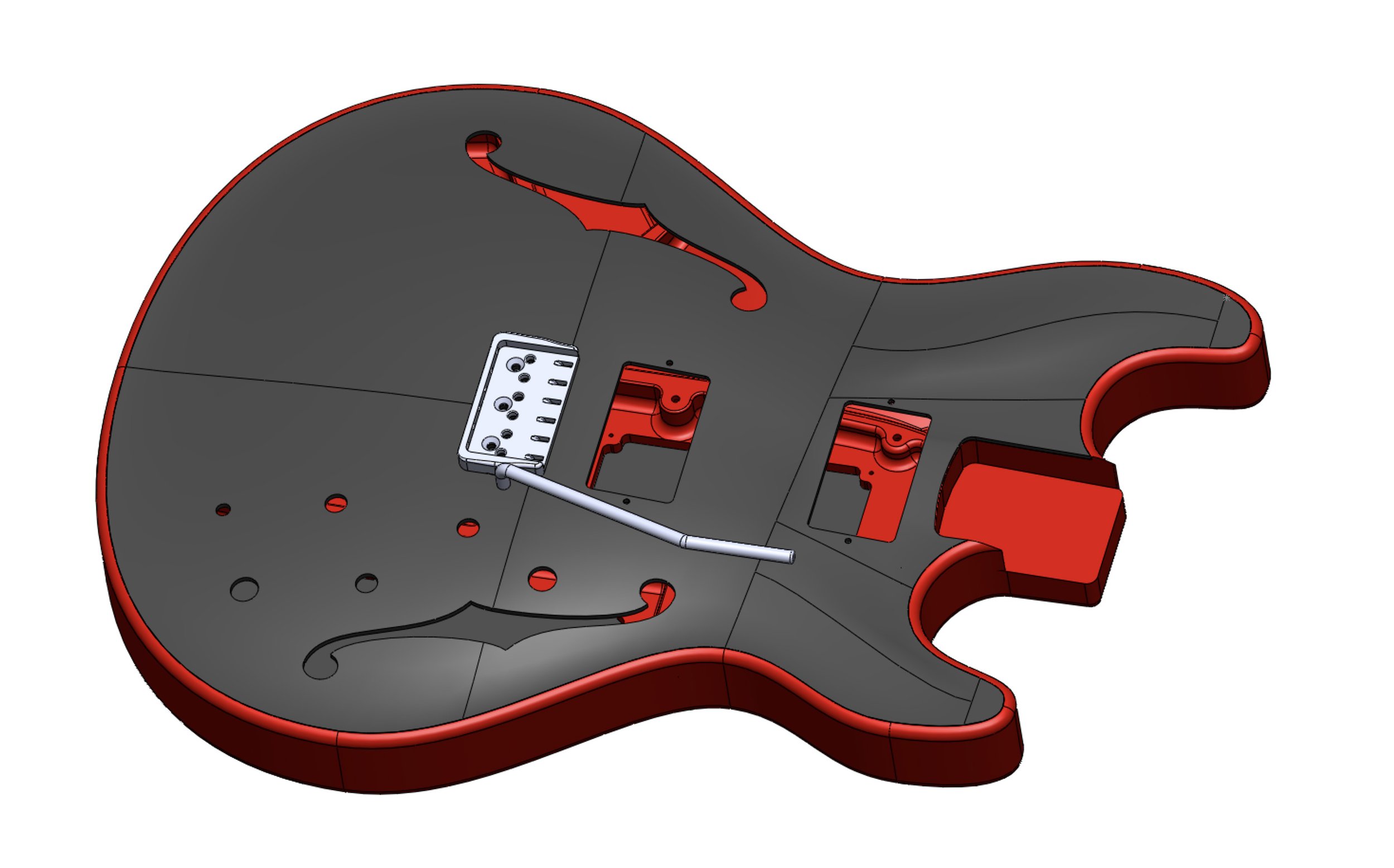
Traditional acoustic bridges anchor the strings below the top, so the strings pull up at the pins and push down on the saddle, creating a twisting force on the top. Now, arches are only strong when compressed, so archtops often use a trapeze tailpiece, so the strings only push down on the top. I wanted a more modern look, so instead of a trapeze I added an aluminum tailpiece mounted to the back of the body. This means the strings will push down and pull forward on the top, but I’m pretty confident the top will be able to handle it. And of course it’s preferable to have string tension squeeze the two parts together rather than ripping them apart. I’m having the tailpiece made unanodized so it’s conductive and can ground the strings if necessary.

A 3d print sits above the tailpiece and serves as a string guide. I intentionally left it super chonky because I have a feeling the body could use more weight for balance. The print doesn’t touch the top so it can vibrate freely.

The string guide doesn’t block the lower mounting point, that’s where the ground wire will attach to the tailpiece. Cover plates will be carbon, of course.
There are no undercuts in this design, so there’s no need to use a 5 axis cnc, which would be more expensive. The only elements that can’t be cut are the neck bolt holes (because of that 2.5 degree neck angle), and the output jack and strap button holes. I’ll have to think up jigs for those to be hand drilled.
I sent off the drawings to the factory. They’ll have to cnc and polish big ol’ steel molds for the arch top, so it was a sizeable investment. Realistically it’s pretty stupid for a non guitar maker to spend all this money on an unproven concept, but I’ve come too far to not see this thing realized. The factory, like me, has no experience with making guitars– they have no clue on woods, much less tone woods, so I had to accept what they had on hand for this first round.
V3
The manufacturing process was pretty extensive, about a 3-4 week process. The smart move would be to sit tight, build the prototypes, and learn from them before making changes. But being of restless mind…
If this is to be an acoustic/electric hybrid, why not push the acoustic aspect of the design farther? A bigger top would sound better and bassier, as would a deeper body. And while we’re at it, why not isolate the top from the pickups? It would let the top vibrate more freely and lighten it as well.
I toyed with a 335 style body, with a carbon top and back (the 335 is symmetrical so the same mold could be used for the front and the back). It would be super swanky, but I couldn’t figure out how to make access panels, which means you’d have to build it by fishing the electronics through the f-holes, which is just insane. Not only that, it would make the whole thing twice as expensive. I also had a hard time meshing the 335 aesthetic with a bolt-on neck.

This was the attempt at the 335 shape. You can see how I’m struggling with the arch top surfacing.
So I went with a hybrid, with the basic shape of a Strat but the size of a 335, 5mm deeper than a Strat.

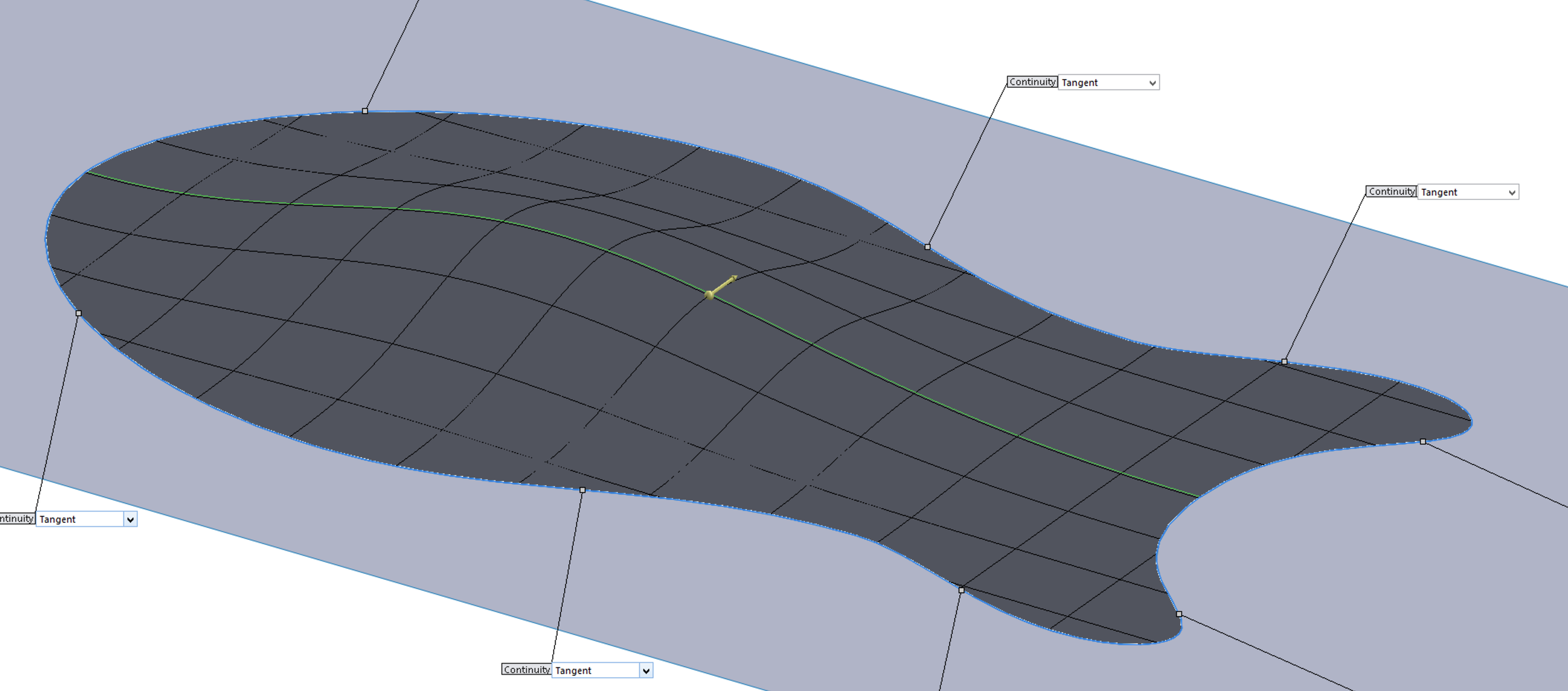
It’s a Strat with a bigger, rounder butt. The green parts are the first two surfaces, which are pretty easy.
This time I wanted to challenge myself and extend the arched profile into the horns. I imagine that there are sculpting programs where you could warp the surface and achieve this relatively easily, but Solidworks is what I know and it’s murder doing this in SW. Here’s the problem: SW likes 4 sided surfaces, so if you want to render a nice surface you have to figure out how to break it up into 4 sided pieces. And those pieces have to flow into each other with smooth tangents, or those pieces won’t stitch together seamlessly. I revisited the tutorials I first watched to learn surfacing, and learned a whole bunch of new things that I wasn’t able to absorb back then.
Armed with my new knowledge I tried again, and after a few days and many failed attempts I got to this point.

Trim it, make some cutouts, and you get here.

The ripples are exaggerated in the rendering, so to be sure the shape was good I printed a half sized mockup so I could put my hands on it.

The layers of the print ends up being a contour map. Pretty close to my original sketch but with a more rounded vibe.
Continuous fibers make the top strong, but pickup holes and f holes sever them. I spec’d the layup to be angled along the lines in the sketch above, so there will be uncut fibers bracing the bridge. Multi-directional grain, something else you don’t get with a wooden top (unless it’s plywood, of course, but then it’s…plywood).
For the top layer of carbon I spec’d a unidirectional sheet. Twill weave is often used for the top layers for aesthetic reasons (the weave just says ‘carbon’), but high end bikes have long moved away from the weave and I think they look better for it. I also thought the unidirectional lines could be reminiscent of wood grain.
As for the back, I added a couple ribs for strength, since this is a bigger body. Posts are also added for mounting the pickups. Pickup height will be adjusted from the back.

Back to Reality
The factory was proceeding along with the V2 body, so I got started on my jigs. I came up with this hole drilling guide that has a pointer to ensure that it’s sitting straight in the neck pocket. I also printed up a ton of clamps for gluing the top.

This is a POS body Amazon sent me by mistake so I used it to test dyes. The pointer will lead to the bridge mounting holes to ensure the jig is aligned.
Prototypes Arrive
After much anticipation three prototypes (2 humbucker 1 single coil) finally arrived…on the day my wife and I left for California to watch our daughter’s college tennis team play. To add insult to injury it rained just enough each day to cancel all the matches. We returned 4 days later and I finally got to put my hands on them.
The carbon tops were incredibly strong, maybe too strong. I made them 3mm, but I think I can go thinner. Like any carbon sheet they rang like a gong. I think most people haven’t held a piece of carbon this big, so this ringing might come as a surprise.
The wooden backs however, were far from stellar. As I said before, my drone supplier doesn’t know wood, and these pieces showed that. The cnc work was perfect but the wood wasn’t dry and stable so they warped and shrank after cutting. By the time they got to me I had to reach inside the body to pry the sides out to get the top on. Leah came over the next day and we built up one for me and one for her. By then the bodies had shrunk even more, so they cracked as we pried the carbon tops on. And we destroyed one when the Forstner bit wandered while we drilled the output jack hole.
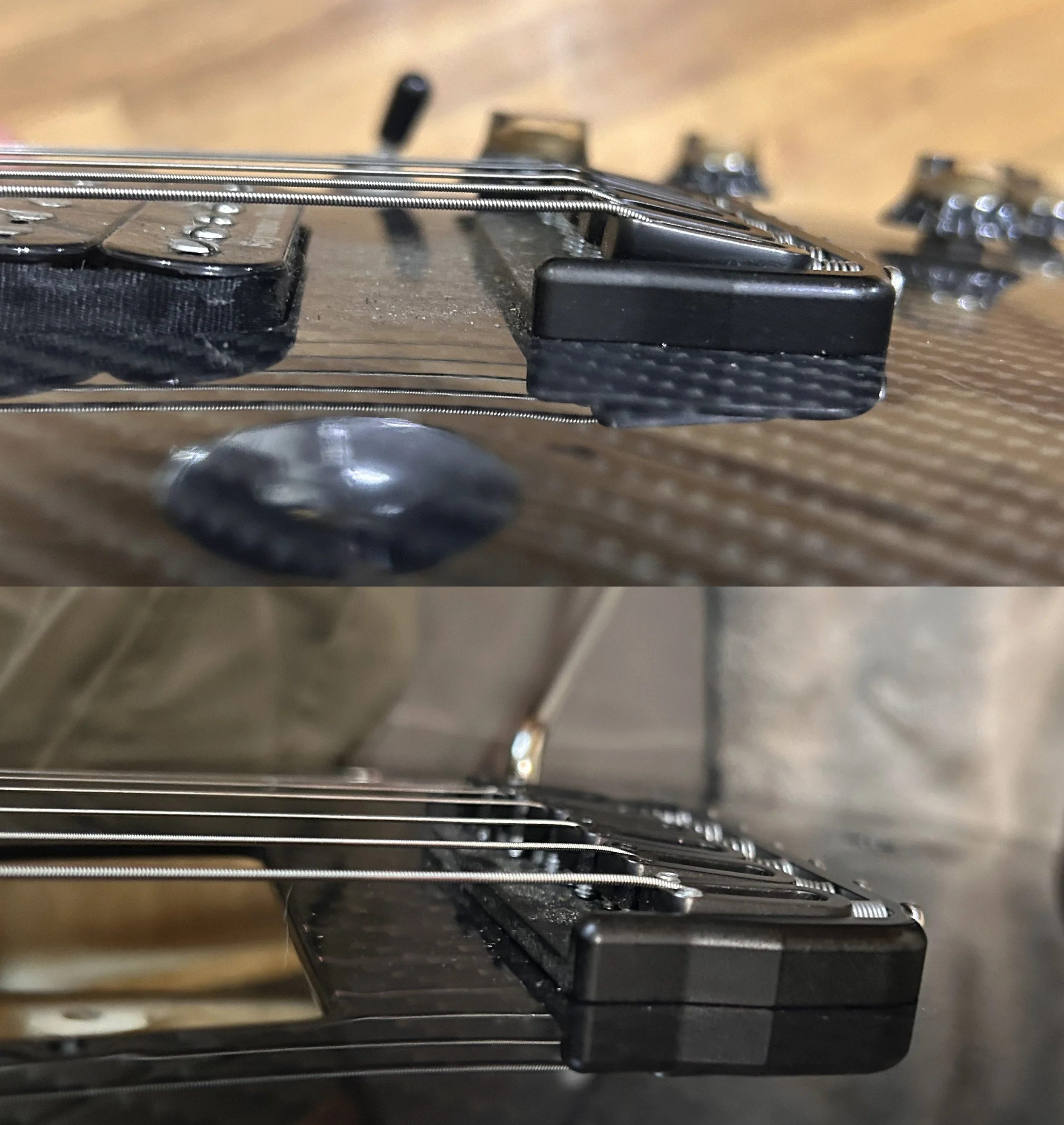
Once built I was able to see my mistakes. The neck isn’t set deeply enough into the body, so the strings sit too high. The Hipshot bridge was maxed out to get the string action high enough. I was able to fix this by shimming the neck to reduce its angle, but it still sits too high in the body. Single coil pickups don’t have much range in height adjustment, so I wasn’t able to get them close enough to the strings. The middle and bridge pickups are ok, but the neck pickup is just too far away to be usable. I also set the bridge a little too far back (I laid it out before I had a saddle in hand), so the saddles were right at the ends of the adjustment screws.

Too much neck protrudes, pickup can’t get high enough. Shimming the neck helped bring the strings down at the bridge, but doesn’t help on this end.
As for electronics, I wasn’t quite ready to figure out a magnetic/piezo blending system, so I ran two output jacks and kept the two systems separate. The magnetics came straight from a Strat so it was all already wired up. The piezos were part of a passive 3 sensor unit with its own output jack, so no wiring needed there either. As expected, the output of the passive piezos were much lower than the magnetics, about equivalent to a 3 on the magnetics.
The guitar was fully functional without the top glued on, since string tension presses the two pieces together. I wanted to know if a solid glue joint would deepen the tone and reduce any buzzing or movement between the two pieces, so I took a shot at epoxying it together. It would be good practice anyway. I ended up making a royal mess of it all. I used too much glue, leading to messy squeezeouts. Also, the body had shrunk even more, so I wasn’t able to fully seat the top. Wrestling the top while it was oozing epoxy was a bit of slapstick worthy of Lucille Ball. I ended up getting it mostly in, and worked the excess epoxy into the many developing cracks.

That’s craftsmanship right there.
So how’d it sound? On the middle and bridge pickups, like a Strat. As for the piezos, I found them a bit thin and squawky, just like they say piezos would sound. But then I brought it to my bike racing friend Paul Carbonara, and in his hands they sounded quite nice.
So that’s Paul on the piezos through a practice amp. Funny how it sounds so much better in a pro’s hands than mine… Paul liked the prototype enough to convince me that this was an idea worth pursuing, so on to V4.
V4
I kept investigating other ways to render the top, and came to the conclusion that my original method was the best. There are easier, more organic ways to get a similar shape, but I needed to be able to locate mounting points precisely in space, so surfacing was still the better way to go.
This seems like it would be easier but it’s just not precise enough.
While chatting with Leah I came to the conclusion that the f holes aren’t really necessary. I thought they might help air move in and out of the cavity and let the top vibrate more freely, but Leah pointed out that the amount of movement of the top is so minimal that the gaps around the pickups would be sufficient for relieving air pressure. I added enough holes for two sets of volume and tone knobs, as well as two toggle switches.
For the back, I added more ribbing for strength, and added posts to mount the pickups. Back mounted pickups should be more resistant to feedback and let the top vibrate more freely. I’d wanted to deepen the body, but the blanks were only available at 42mm. With that I ordered three more, for Leah, Paul, and me, two with Tele neck pockets and one Strat. This is a new top, so that’s a new mold and more $$$.

I asked the factory to contact guitar makers to source the wood, so they were able to get properly dried mahogany blanks. Leah suggested trying using twill weave instead of unidirectional for the carbon top layer. The first tops looked a little bland.
Once the backs were cut I had the option of having them finished, but it would take another two weeks. I opted to have one finished and two delivered asap.
The first two arrived and the new carbon tops were stunning. Then the finished one arrived while I was still applying Tru Oil to the first two, and it was even prettier.
I was having fun with the Tru Oil finishes, but they still paled in comparison.

As for electronics, Leah simply transferred her parts over from her original build, with no piezos. I got some Seymour Duncans and another 3 way switch to run the magnetics and piezos to the same jack.

That’s Josh’s on the top left, mine on the bottom right, and Paul’s on the bottom left.
The middle position blending the magnetics and piezos had an interesting tone, with the magnetics filling out the piezo squawk. The magnetics had to be dialed down to about 3 to properly blend them, however. So for Paul’s build I looked into adding a preamp for the piezos. I bought an LR Baggs and a Graphtech and set about trying to understand their wiring. The LR Baggs made a bit more sense at first so I put it in Paul’s build. It was a bit of an adventure, and it took a little trial and error to get all the knobs to function.

The three black disks are the piezos.
With that done it was time to glue it up and finish it. Paul had a Warmoth neck lying around and boy did it make a pretty build.


Looka that flame maple neck!
Paul’s build sounded a little better than mine, but the piezo output was still lower than the magnetics. I’m guessing the LR Baggs was made for under the saddle piezos, and just doesn’t match the output of the disk piezos I used. Still, some progress.
I kept studying up on piezos and realized that I could use the Graphtech preamp I already bought with their saddle pickups. I really wanted to use disks on the top – I’d gone to so much trouble to make a cool top it seemed stupid to not mount piezos on it. Saddle pickups bypass the top, but I’m hoping the fact that they’re mounted to a lively top would enrich their sound nevertheless.
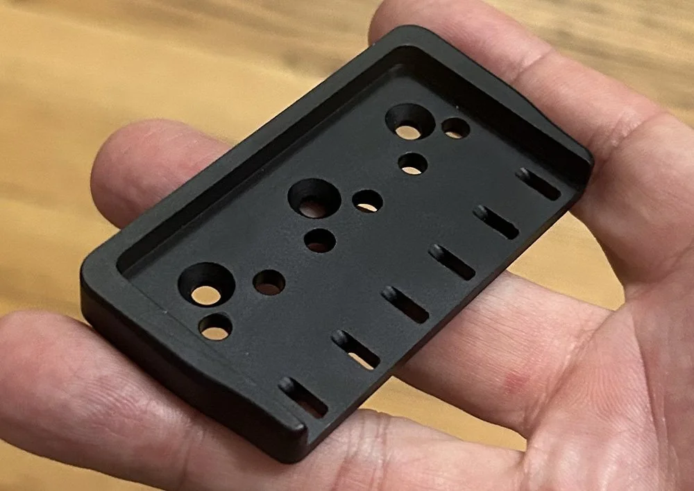
I drew up a bridge plate to hold the Graphtech piezo saddles. It’s pretty similar to the Hipshot, but with holes for the wires from the saddles to enter the body.
When Paul played V3 he busted out some country licks, and remarked that it really had a Tele tone. That got me thinking: was that because of the super stiff carbon connection between the bridge and the bridge pickup, like the metal bridge plate on a Tele? Then I thought about how so many electrics have pickups mounted to a piece of plastic. It seems silly to obsess about tone woods when there’s a weak link in the chain in the form of a pickguard or mounting ring. Maybe it’s better to have pickups mounted to a super stiff super resonant carbon top, with no weak links in the signal chain. Hopefully the hollowbody tone would come through the pickups.
V4’s, with pickups mounted to the back and isolated from the top, didn’t sound noticeably better than V3’s acoustically, so maybe it does no harm to mount the pickups to the top. Besides, installing the pickups to the back was a real pain. I added mounting holes to the top so I could build the next ones either way.

Then I got the crazy idea of adding a springless tremolo, by simply flexing the top. I added f holes to isolate the bridge from the sides and make it more flexible, and added a block under it for a 6mm bar to screw into. It’s a totally crazy idea and I’d be surprised if it changed the notes even a half stop, but it’s a quick and relatively inexpensive experiment. And it looks kinda cool.


There’s the block that the bridge screws into.
The files went off to the factory and it was time for another long wait. In the meantime I started designing a bass.
V5
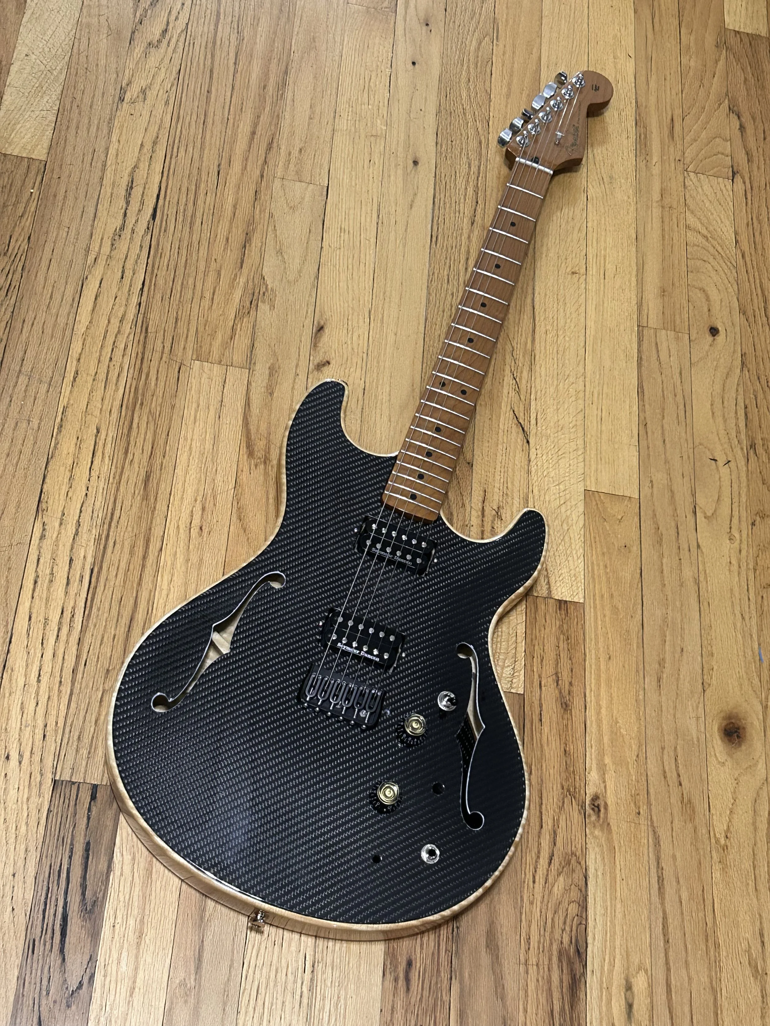
The next batch came in and the backs were gorgeous!
My excitement was quickly dampened when I realized I made a mistake on the piezo bridge.
I’d forgotten to add holes for the saddle adjustment screws. This meant I couldn’t build it up with the piezo saddles until I got this fixed. I could, however, build it up with a regular Hipshot bridge and test the trem bar. I took apart the V2 build and used the neck and bridge to quickly cobble together an ‘acoustic guitar’, with the top unglued (it functions perfectly unglued). Incredibly, the trem worked! It’s good for about a half stop, so it’s just a ‘shimmer’, not a dive bomb. But it definitely works and it really seems the carbon is more than strong enough to take the stress (there are bike suspensions that use a carbon spring after all). I’ll keep bashing away at it of course but it really does seem like the top is utterly unbothered by the flexing. I just love that it’s a trem system devoid of moving parts.
The saddles were close to being maxed out on height on the previous iteration, so I reduced the neck angle by half a degree. This put the saddles right in the sweet spot.
Before and after. Saddles nice and low now.
I’d been vacillating on f holes, not sure if they’re necessary. But with this version where they function as a break between the bridge and the edges of the top (to make the top more flexible for the trem), I have to say the guitar as a whole is so much prettier. They’ve got to stay.

Acoustically this one is brighter than the last, with the only differences being the f holes and the big aluminum block under the bridge. I wanted to see how difficult it would be to build if you got the body pre glued, so I soldered up the components on one of the other tops, and transferred them over. I even left the strings on. The pickups were slightly finicky to install but definitely doable. It was helped by using some silicone tubing on the screws instead of the usual super long springs.

I intentionally used all the same components on this build so I could do a side by side tone comparison. I noticed that this new one is even twangier than the first, more Telecaster than a Telecaster. My theory about the Tele bridge plate might have some merit. On a purely aesthetic front, I didn’t like how the f holes get lost so I painted the edges with a paint pen. A little ghetto but it works.
Paul was using his in a show at the Axis Theater. I attended a rehearsal and brought the new one for him to check out. He liked it enough to commandeer it, and I asked him to compare it to his original guitar. He agreed with me, it’s pretty similar, but brighter, and he liked the tremolo.
I thought that by mounting the pickups directly to the top it would be jazzier and mellower like a traditional wooden arch top, but the carbon is so stiff and rigid that if anything, it got crisper and sharper (Leah uses the words ‘direct’, ‘quick’, and ‘loud’). I think it’s funny that I started out trying to make an acoustic/electric hybrid hollowbody, but might’ve ended up with something more like a solidbody, but even brighter. It is, however, a bit more prone to feedback than a solidbody. I really wonder how those Graphtech piezos will sound.

Paul trying the new one. He stuck with the original for the show because he’d grown so accustomed to it. I moved the volume knob slightly on the new one and it made it harder for him to do volume swells. Luckily switch and knob positions are easily changed.

Stolen shot from Axis.
Piezos
The fixed bridge plates came in and it was time to install the Graphtech piezo saddles. The instruction manual looked incredibly daunting but once I figured it out it was actually dead simple. You basically plug all the components into the board, wire in the signal and ground from the magnetics, and then solder the output to the jack. It’s a really well made system. I had a mild scare when I used the bluetooth dongle from my Boss Katana and got no sound from the piezos. Leah explained that the dongle has a stereo jack, and that I needed a mono jack to power up the 9v for the preamp, and then all was good.

Looks scary as hell but ended up being quite intuitive.

The piezo saddles. Each saddle has a wire that enters the body through the bridge. I added a 3d printed collar to the whammy bar to keep it from swinging around.

From right to left, 3 way switch for the magnetic pickups, magnetic volume, piezo volume (it’s a push-pull pot that selects between two piezo tones), magnetic tone, 3 way switch to choose between magnetics and piezos.
The Graphtech piezos turned out to be fantastic, so much better than the piezo disks I used on the previous round. First of all, the output matches the magnetic pickups perfectly (the disks never matched the magnetics in output). The push/pull pot gives you a bright and a dark tone, both totally useable, unlike the thinner disk tone that needed some magnetic tone blended in. They do a decent job of imitating an acoustic, but the real cool thing is that they’re just nice pickups, good for clean tones and some gain. And with all the pickups on, you can blend the two sounds using their respective volume knobs. I brought it over to Paul to run through some tones.
To be continued…